Base Units - Worktops and Breakfast Bars - Island Worktop


| Previous - Customising Units. | Return to Index. | Next - Multi-range designs. |
Attachment is a catch-all term for items that are automatically attached to your design i.e. worktop, cornice, pelmet and plinth.
Most units in ArtiCAD have some form of attachment. When you add a unit ArtiCAD works out the shape of the attachment for you and adds it to the design as part of that unit. The shape of the attachment will follow the shape of the unit.
You will encounter situations where you will need to specify the shape of the attachment yourself.
NOTE - it is not always necessary to create a custom worktop. In many situations the Island Worktop is sufficient to create the worktop shape or colour you require. Don't make your design more complex than it needs to. Some examples of using Island Worktop are included at the end of this chapter.
To create an Island Worktop:
Base Units - Worktops and Breakfast Bars - Island Worktop
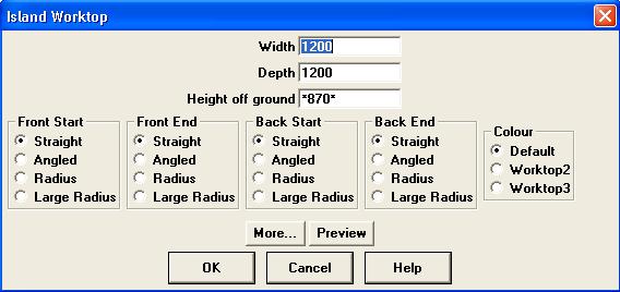
Width, Depth and Height off ground are specified same as for any other unit.
If you were to look at the worktop you are creating, front refers to the edge closest to you. Start refers to the left-most point of that edge. End refers to the right-most point.
Each corner of the worktop can be changed to one of four styles:
Once you have specified the dimensions and style of the worktop, click "OK" to add it to your design.
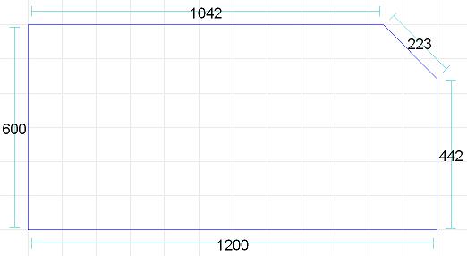
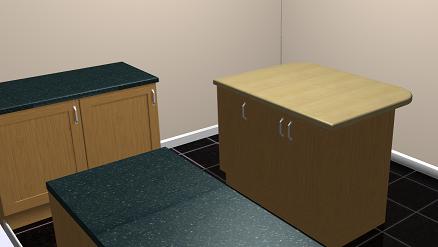
Example 1. Extending the worktop on an island.
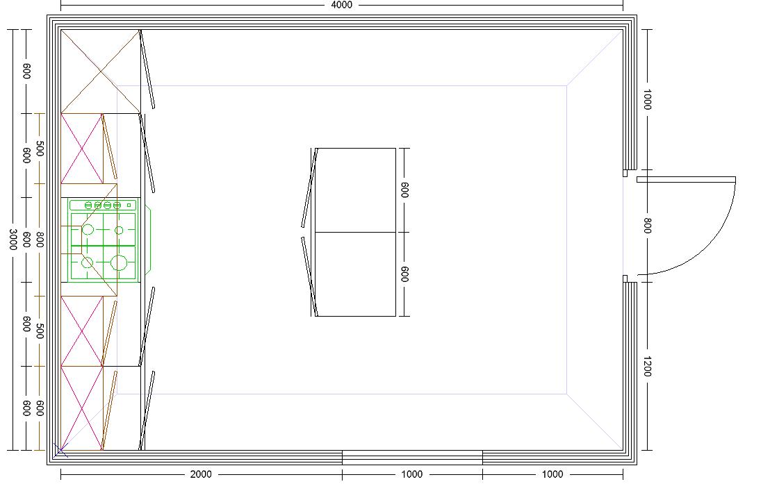
Using the above plan as an example, we will extend the worktop from the back of the island by 300mm. We will also apply a radius to the corners.
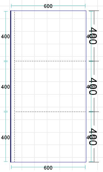
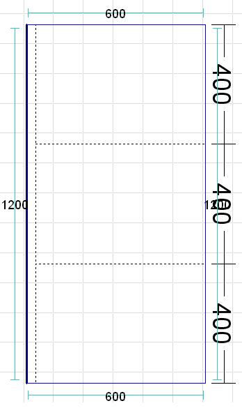
Create the island worktop.
Width - 1200.
Depth - 300.
Front-start - radius.
Front-end - radius.
Back-start - straight.
Back-end - straight.
Colour - Default.
Click "OK" to add it onto your design. Position using Drag and Drop.
NOTE - the dimension for the width of the Island Worktop running along the back. In this example the back of
the Island Worktop is against the back of the units making up the island.
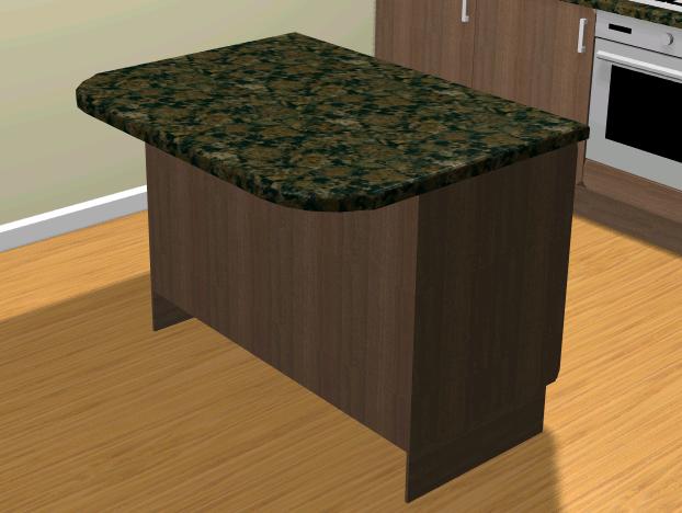
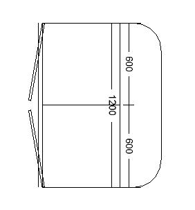
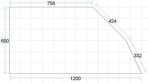
Example 2. Replacing the worktop on an island with worktop in a different colour.
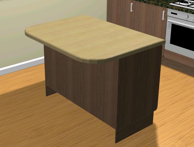
We will replace the worktop on the two units making up the island, as well as extending it by 300mm and radiusing the corners.
Remove the existing worktop by editing the units making up the island and un-selecting "Has Worktop". This will stop the new Island Worktop clashing with the default worktop. For more complex islands bear in mind that end panels and showback panels will also have worktop attached.
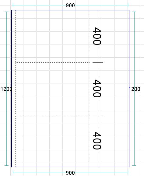
Create the island worktop.
Width - 1200.
Depth - 900.
Front-start - straight.
Front-end - straight.
Back-start - radius.
Back-end - radius.
Colour - worktop2.
Click "OK" to add it onto your design. Position using Drag and Drop.
The colour of this Island Worktop has been set to "worktop2". The colour of "worktop2" can be changed under "This Design" - "Photo Realism Colours. For details on changing colours see Changing colours.
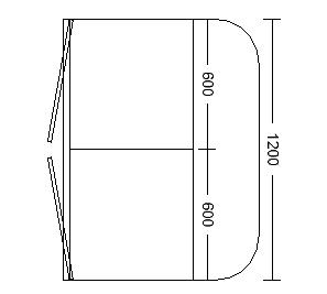
NOTE - the dimension for the width of the Island Worktop running along the back (the end with the radius). This way the dimension does not
overlap the doors at the front of the island.
Custom attachments have many uses. These include (but are not limited to):
The method used to create the shape for your attachment outline is the same for all room systems.
| Kitchen - Worktop or Panel |  |
 |

|
| Kitchen - Cornice, Pelmet or Plinth |  |
 |
 |
| Bathroom - Worktop or Panel |  |
 |
 |
| Bathroom - Cornice, Pelmet or Plinth |  |
 |
 |
| Bedroom - Worktop or Panel |  |
 |
 |
| Bedroom - Cornice, Pelmet or Plinth |  |
|
|
Select the type of attachment you want to create.
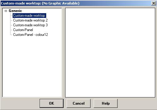
The above image shows the options for the Custom Worktop in the Kitchen room system.
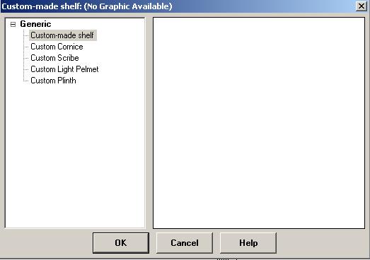
The above image shows the options for the Custom Shelf in the Kitchen room system.
Select the type of attachment you wish to create and click "OK".
The properties of the attachment depend on the type you have selected.
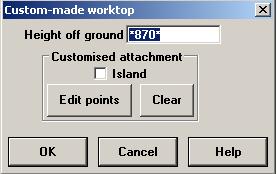
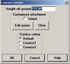
The first image shows the properties for a Custom Worktop, the second shows properties for a Custom Cornice. The properties vary from attachment to attachment.
Make any changes you require then click "Edit Points" to start drawing your new attachment.
IMPORTANT - clicking "OK" will skip the drawing step and place a zero-sized (i.e. 0 x 0) attachment onto your design.
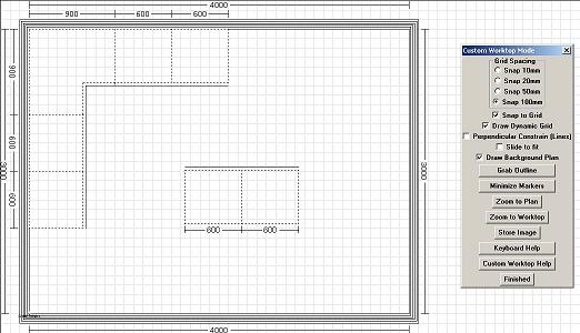
The custom attachment drawing screen.
Mouse controls.
Keyboard controls.
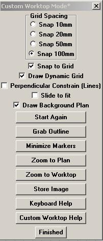
The Custom Attachment toolbar.
You must draw a complete outline for your custom item. When you have a complete outline the mouse pointer will change from "New" to "Edit".
An outline must consist of a minimum of 3 seperate points. There is no upper limit on the size of an outline or the number of points making up the outline.
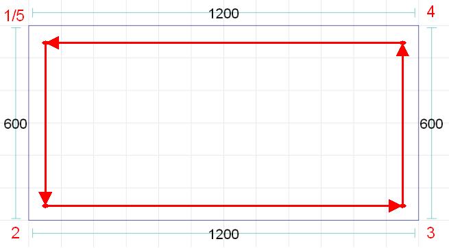
The above image shows the order in which the points were created (denoted by the red arrows), starting with point 1 and ending with point 5 (i.e. back where the outline started).
IMPORTANT - You must draw the outline anti-clockwise - if you draw clockwise you will find the dimensions for your attachment on the inside of the outline.
You must have a complete outline before being able to edit it i.e. it says "Edit" and not "New" under the mouse pointer.
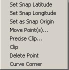
Right-click on a point to bring up the following options:
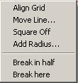
Right-click on a side to bring up the following options:
This is covered in Setting Up Your Design - Attachments. The attachment you need to change will depend on which attachment you select i.e. if you are using "worktop2" change the attachment for "Worktop2", if you are using "plinth3" change "Plinth3".
Method 1 - drag with the mouse.
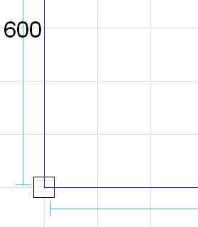
Move your mouse over the point you wish to move. A box will appear around the point (as shown above). Hold down the left-mouse button and drag the point into position. NOTE - if "Snap to grid" is selected, the point will jump to the nearest grid-square.
Method 2 - specifying the distance to move.
Move your mouse pointer over the point you wish to move. A box will appear around the point (shown above). Right-click on the point and select "Move Points...".
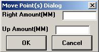
Specify the distance, in millimeters, you wish the point to move. To move to the left or down the screen, enter a negative value. NOTE - the point will not snap to the nearest grid square, even if "Snap to grid" is selected.
Both of the above methods work with multiple points selected. See "Selecting multiple points".
Method 1 - drag with the mouse.
Move your mouse over the side you wish to move. The side will turn red (as shown above). Hold down the left-mouse button and drag the side into position. NOTE - if "Snap to grid" is selected, the side will jump to the nearest grid-square.
Method 2 - specifying the distance to move.
Move your mouse pointer over the side you wish to move. The side will turn red (shown above). Right-click on the side and select "Move Line...".
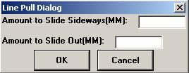
Specify the distance, in millimeters, you wish the side to move. "Sideways" is relative to the direction the side is running in. "Out" will move the side away from the center of the outline. In the above example a positive sideways value will move the side down, and negative value will move it up. A positive out value will move it to the left, and negative value to the right. NOTE - the side will not snap to the nearest grid square, even if "Snap to grid" is selected.
There are two methods for selecting multiple points on your outline. You must have a complete outline to select points i.e. it says "Edit" beneath the mouse pointer. Once you have multiple points selected, any changes made will be applied to all the selected point.
Method 1 - using the keyboard. Select one of the points making up your outline. Pressing "F7" will select the next point (based on the order the points were initially drawn) as well as the point currently selected. Press again to select the next point, and so on until you have all the points you require selected.
Method 2 - using the mouse. Hold down the left mouse button and drag the mouse. Drag the select box around all the points you wish to edit, then release the mouse button.
Move your mouse over the point you wish to delete. Right-click and select "Delete Point". The outline will then redraw itself without that point.
In this example, we will delete the bottom-left point.
This example will cover the various ways of clipping a corner on your attachment.
Starting with the following outline
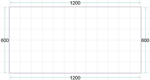
We will clip the top-right corner.
Method 1 - right-click on the corner you wish to clip and select "Clip".
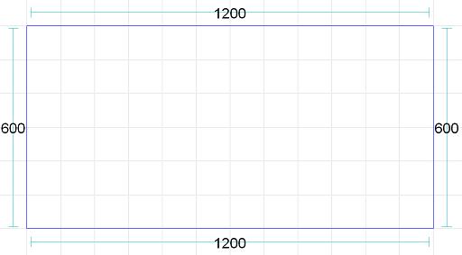
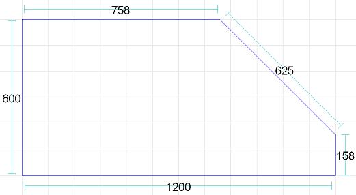
The corner has been clipped by half the length of the shortest side leading into the selected corner i.e. the 600mm running down the right-hand side of the outline.
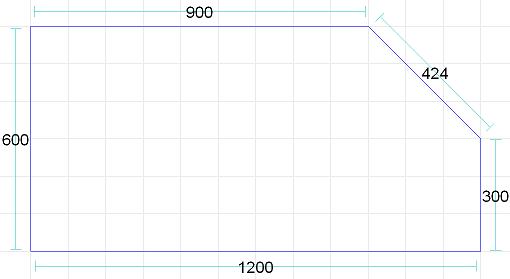
Method 2 - right-click on the corner you wish to clip and select "Precise Clip...". You will then be prompted for the distance you wish to clip the corner back. In the above image the clip distance was set to 300.
Slide to fit - if selected on the Custom Attachment Toolbar, you can re-size the clipped corner by holding down the left-mouse button and dragging the corner to the correct size. If "slide to fit" is not selected, the clipped corner will behave as a normal side of an outline.
"Slide to fit" has the same effect on clipped corners created using "Clip" or "Precise Clip...".
Clipped corner dragged left then right with "Slide to fit" selected.
Clipped corner dragged left then right without "Slide to fit" selected.
Right-click on the corner you wish to radius and select "Curve corner".
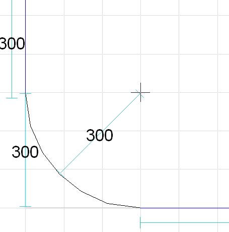
There are two methods of adjusting the size of the radius.
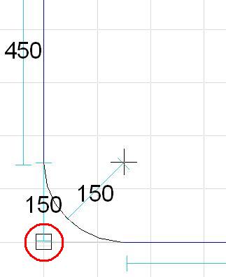
Note that the original corner (circled in red) remains even after the corner has been radiused.
Method 1 - select the corner you wish to radius. Press "F1" to create the initial radius (defaults to 150mm). Press "F1" to reduce the radius, "F2" to increase.
Method 2 - right-click on the corner and select "Specify radius" or alternatively select the corner and press "F9".
Enter the required radius and click "OK".
You can mix the two methods as required e.g. right-click on the corner to create the curve, then use F1/F2 change the size.
These methods also apply when multiple points are selected.
Right-click on the side you wish to radius and select "Add radius".
There are two methods of adjusting the size of the radius.
Method 1 - drag the radius selector (circled in red, above) to the required radius.
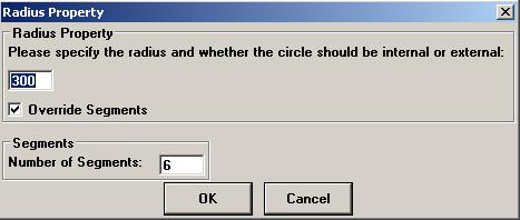
Method 2 - right-click on the radius selector (circled in red, above) and select "Specify radius".
Enter the required radius and click "OK".
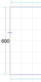
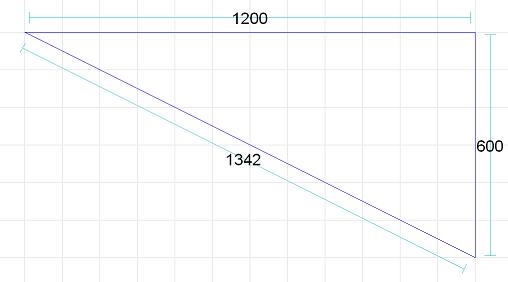
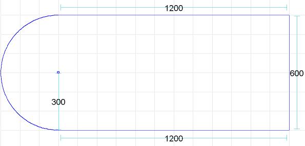
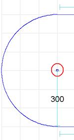
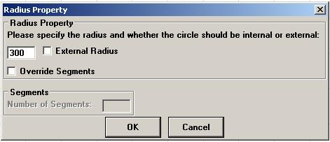
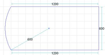
The radius defaults to half the length of the selected side. To create a gentle curve or bow-front style worktop, increase the radius. The below image shows a 600 radius. The exact value of the radius will vary according to the size of the outline.
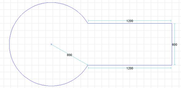
Selecting "External Radius" will create a circular addition to the outline, based on the specified radius. If the radius is too small this option will automatically turn itself off.
Override segments allows you to change the number of steps used to create the external radius outline. More steps gives a smoother outline, fewer steps gives a faceted look.
Using the below design, we will replace the worktop on the island (3 x 400 units) and extend it to create a simple breakfast bar.
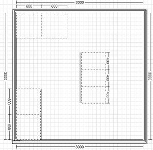
Start a new Custom Worktop. Use "Custom-made worktop 2" and select "Island" before clicking on "Edit points".
Click on the "Grab Outline" button on the Custom Atrtachment toolbar until the outline of the island is selected.
Note that the long sides of the outline are made up of three 400 lengths of worktop, not a single piece. Click on "Minimize markers" to reduce the outline to the minimum number of pieces.
Extend the worktop over the back of the units by 300mm. Right-click on the side, select "Move line..." and specify a "Distance to move out" of 300.
Apply a radius to the corners of the overhanging worktop. Right-click on the corner and select "Curve Corner".
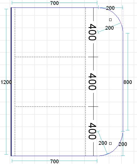
Add the newly created worktop onto the design by clicking "Finish".
To change the colour of the worktop, click "This Design" - "Photo Realism Colours" and edit "worktop2".
Return to top.